First, the basic structure of mechanical feedback servo valve
Mechanical feedback servo valve usually consists of valve body, main spool, pilot valve, torque motor (or electromagnetic coil), feedback lever and spring. Its working principle is to control the electric signal to drive the electromagnetic coil to generate magnetic force, push the pilot spool to move, and then change the position of the main spool to realize accurate control of the flow and pressure of the hydraulic system. The mechanical feedback is connected with the main valve core through the feedback lever, and the displacement of the valve core is fed back to the pilot part to form closed-loop control and improve the stability of the system.
Second, the preparation before connection
Before connecting the mechanical feedback servo valve, the following preparations should be made:
1. Confirm the system parameters: including working pressure, flow rate, control voltage/current, oil cleanliness level, etc., to ensure that the servo valve matches the system.
2. Check the cleanliness of the oil circuit: impurities in the hydraulic system may damage the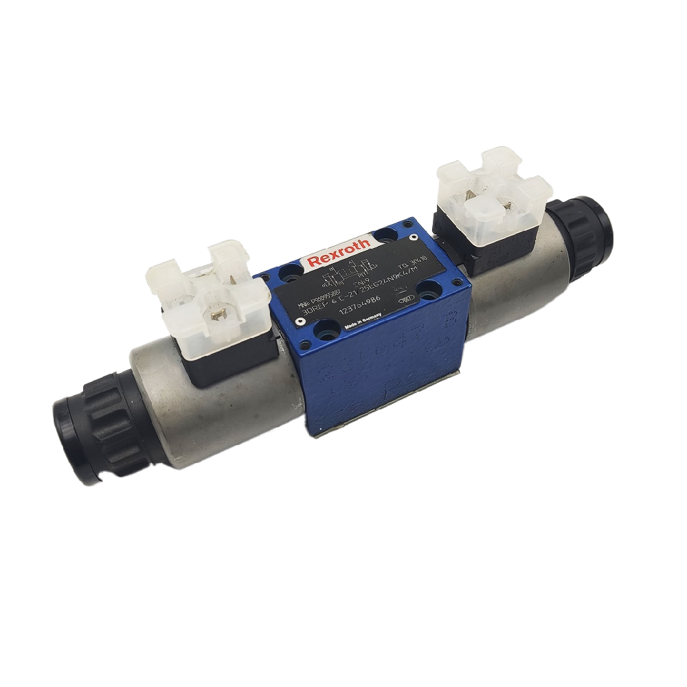 internal precision parts of the servo valve. Before connection, make sure that the pipeline, oil tank, filter and other parts are clean.
3. Prepare connecting elements: such as high-pressure hoses, joints, sealing rings, fixing brackets, etc. to avoid oil leakage or looseness during installation.
Third, the mechanical feedback servo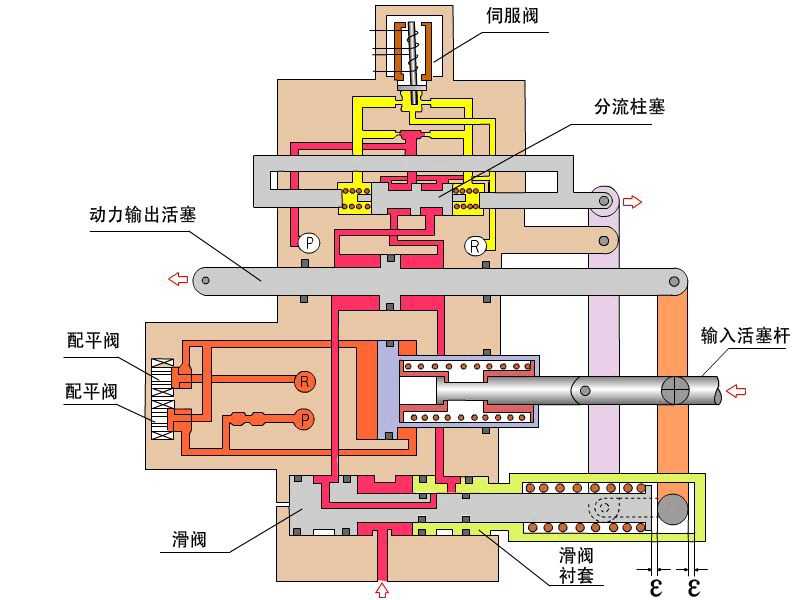 valve connection steps
1. Determine the installation location
Generally, the servo valve should be installed near the actuator (such as hydraulic cylinder or motor) to reduce the response delay. At the same time, ensure that the installation surface is flat and firmly fixed with bolts to prevent displacement or leakage caused by vibration.
2. Connect the oil inlet and outlet
Connect P (pressure port), T (oil return port) and A/B (working port) correctly according to the nameplate or manual of the servo valve. Pay attention to the use of suitable sealing rings and avoid the damage of sealing rings caused by excessive tightening.
3. Connect the electrical interface
Connect the control signal output by the servo amplifier to the electromagnetic coil of the servo valve. Pay attention to the correct polarity to prevent the reverse connection from burning the coil. At the same time, the shielded cable should be well grounded to reduce electromagnetic interference.
4. Connect the mechanical feedbac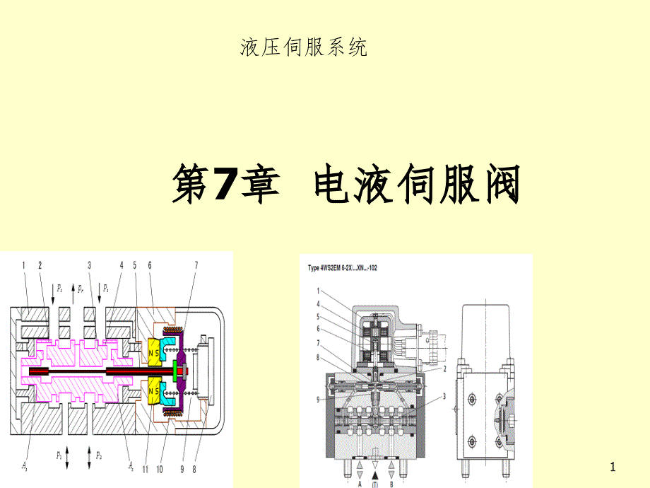 device
This step is the key to the connection of mechanical feedback servo valve. The feedback lever is usually connected to the main valve core through a pin shaft or a connecting rod, and the other end is connected to an actuator or a position sensor. Adjust the length and angle of feedback lever to ensure the accurate transmission of feedback signal and make the system form closed-loop control.
5. System debugging
After installation, debug the system, gradually load the pressure and flow, and observe whether the servo valve responds sensitively and moves smoothly. Adjust the gain of feedback device or amplifier if necessary to optimize the system performance.
Four, connection matters needing attention
-Avoid connecting the oil port by mistake: connecting the oil port by mistake may cause the servo valve to be damaged or the system out of control.
-Prevent air blockage: exhaust fully before initial operation to prevent air from entering and affecting control accuracy.
-Regular inspection and maintenance: regularly check whether the connection parts are loose and the oil seal is aging, and replace the filter in time to prolong the service life of the servo valve.
-Keep the control signal stable: It is recommended to use a regulated power supply and a high-quality servo amplifier to ensure the stability of the control signal.
tag
Correct connection is the basis of stable operation of mechanical feedback servo valve. Through reasonable installation, accurate connection of feedback device and system debugging, the control performance of servo valve can be fully exerted, and the accuracy and efficiency of the whole hydraulic system can be improved. In practical application, it is necessary to flexibly adjust the connection mode according to the specific equipment requirements to meet the control requirements under different working conditions.