High-frequency servo valve is the core control component in hydraulic servo system, which is widely used in aviation, aerospace, precision manufacturing and other fields that require high dynamic response. Its response speed and control accuracy directly affect the performance of the whole system. Therefore, how to accurately measure the response characteristics of high-frequency servo valve is the key link to evaluate its performance and optimize the system design.
First, the basic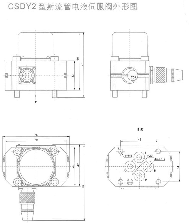 working principle of high frequency servo valve
High-frequency servo valve controls the flow and direction of hydraulic oil by receiving electrical signals (usually current or voltage signals), so as to achieve high-precision control of the position, speed or force of actuators (such as hydraulic cylinders or motors). Its core features are fast response, high control accuracy and stable operation under high frequency conditions.
Common high-frequency servo valves include nozzle flapper valve, jet pipe valve and other structural forms, and their response frequency can usually reach hundreds of hertz or even higher.
—
Second, the key indicators of servo valve response characteristics
When measuring the response of servo valve, we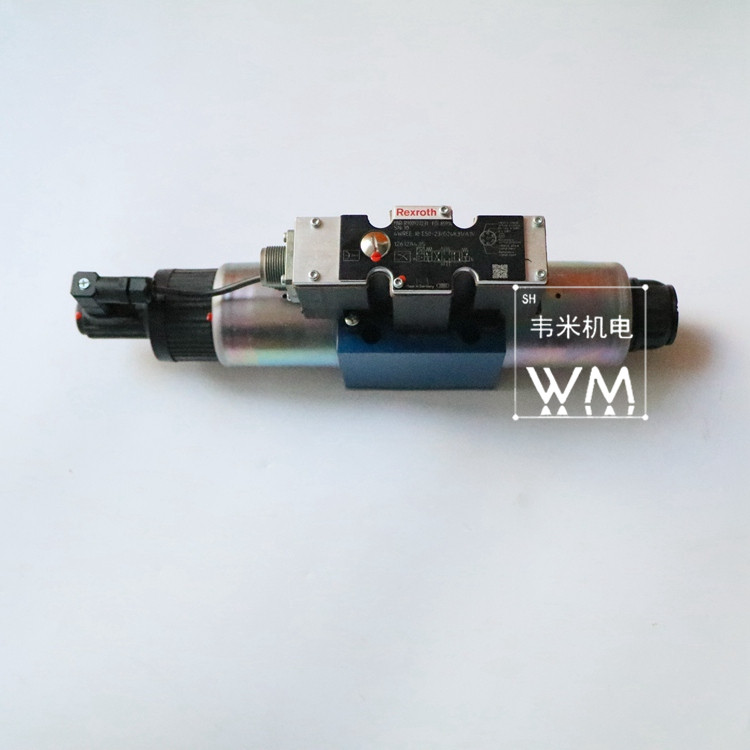 mainly pay attention to the following performance indicators:
1. Bandwidth: usually defined as the frequency corresponding to the servo valve when its amplitude decays at -3dB, which reflects its ability to track high-frequency signals.
2. Phase Lag: It measures the time delay of the valve output relative to the input signal at different frequencies.
3. Step response time: including rise time, adjustment time and other indicators, reflecting the rapid response ability of the valve under sudden signal.
—
Third, the measurement method of high frequency servo valve response
# 1. Sine frequency sweep method
Sinusoidal frequency sweep method is one of the most commonly used methods to measure the bandwidth and phase characteristics of servo valves. The specific steps are as follows:
-Input a sinusoidal current signal with adjustable frequency to the servo valve;
-collecting the output signal of valve outlet flow or pressure;
Analyzing the amplitude and phase of the output signal by Fourier transform;
-Draw Bode diagram to get the frequency response curve of servo valve.
This method can fully reflect the dynamic performance of servo valve at different frequencies, and is suitable for accurate measurement under laboratory conditions.
# 2. Step response method
The step response method records the time required for the servo valve to output from the initial state to the steady state by inputting the step electrical signal. The main indicators of concern include:
-Rise Time (rise time)
-Peak Time (peak time)
-setting time (Settling Time)
-Overshoot (overshoot)
This method is easy to operate and suitable for quick evaluation of the basic response characteristics of servo valves in the field.
# 3. Pulse excitation method
Pulse excitation method excites the servo valve by inputting short-time current pulse, and captures its transient response curve by using high-speed data acquisition system. By analyzing the characteristics of the response curve, the dynamic parameters of the system can be further calculated.
—
Four, the key equipment of the measuring system
In order to ensure the measurement accuracy, the following key equipment shall be equipped:
-signal generator: providing an input signal with controllable frequency and amplitude;
-Power amplifier: used to amplify the current or voltage to drive the servo valve to work;
Sensors: including pressure sensors, flow meters or displacement sensors, for detecting output signals;
-High-speed data acquisition system: used to synchronously acquire input and output signals, which is convenient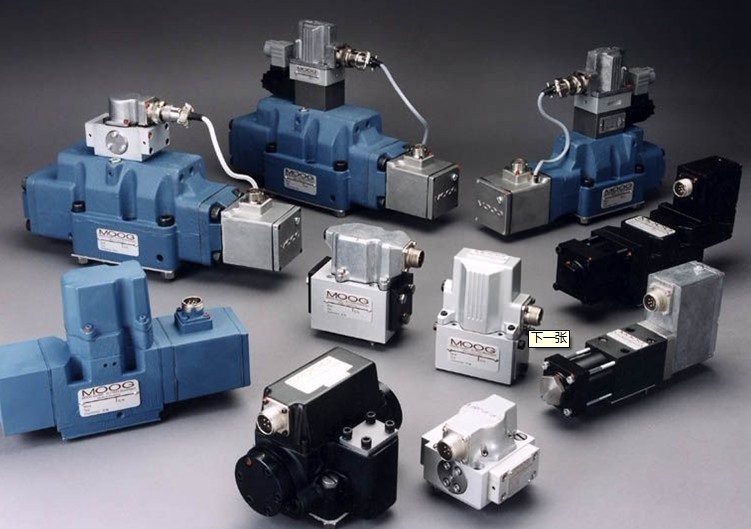 for frequency domain and time domain analysis;
-Signal analysis software: such as MATLAB and LabVIEW, used to draw Bode diagram and analyze step response curve.
—
Five, the factors affecting the measurement results
In actual measurement, the following factors may affect the accuracy of the measurement results:
-Signal-to-noise ratio of input signal;
-Whether the bandwidth and response speed of the sensor match the servo valve;
-oil temperature and pressure stability of hydraulic system;
-Whether the installation position of the valve and the length of the pipeline cause additional dynamic delay.
Therefore, these interference factors should be controlled as much as possible in the measurement process to ensure the reliability of the data.
—
VI. Conclusion
With the development of modern control technology, the requirements for servo valve response speed and accuracy are getting higher and higher. The scientific measurement method can not only evaluate the performance of the servo valve itself, but also provide an important basis for the optimal design of the hydraulic servo system. In the future, with the development of digital signal processing technology and intelligent measuring equipment, the measurement of high-frequency servo valve response will be more efficient and accurate, which will provide strong support for the automatic control of high-end equipment.